
Dual-Clamp Digital Phase Meter
General Information:
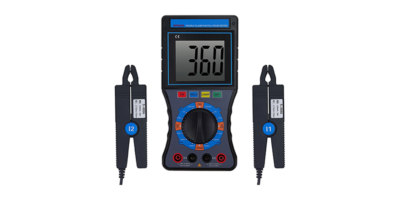
EP8420 Dual-clamp digital phase meter is a multi-functional instrument developed specially for on-site test. Featured with high precision, good stability, less power consumption and easy operation, it measures directly A.C. voltage and A.C. current even when the tested circuit is not opened, as well as phase between two voltages, two currents and the voltage-current. In addition, it measures indirectly power factor and power of the circuit, identifies three-phase sequence, wiring group, inductive and capacitive circuit of transformer, tests secondary circuit and the busbar differential protection system, tells the phase relation between different CT groups of differential protection, examines whether the wiring of watt-hour meter is correct, and checks and repairs circuit equipment, etc. The instrument has huge LCD screen, with letters reaching 40mm in height and looks greatly clear thanks to the backlight design. The instrument is applicable to electricity, petrochemical engineering, metallurgy, railway, meteorology, industrial and mining enterprises, academic institutions, colleges and metrological sectors, etc.
Technical Specifications
Reference Conditions and Operating Conditions
| Influence Factors | Reference Conditions | Operating Conditions | Remarks |
| Ambient environment | 23℃±1℃ | -10℃~40℃ | |
| Ambient humidity | 40%~60% | | |
| Signal waveform | Sine wave | Sine wave | β=0.05 |
| Signal frequency | 50HZ±1HZ | 45HZ~65HZ | |
| Working voltage | 9V±0.1V | 9V±1V | |
| Phase current range applicable | 1A±0.1A | 10mA~20.0A | |
| Phase voltage range applicable | 100V±10V | 30V~600V | |
| External electric field and magnetic field | Shall be avoided | ||
| Location of tested wire | The tested wire is located in approximate geometric center of the clamp jaw | ||
General Specifications
| | Directly test phase, A.C. current, A.C. voltage, A.C. leak current, and phase sequence; identify grouping, inductive, and capacitive circuit of transformer; and indirectly test power factor and power. |
| Power Supply | DC9V alkaline dry batteries (1.5V AA×6) |
| Power Consumption | Nearly 35mA at the maximum if backlight on, batteries work continuously for nearly 40 hours. |
| Nearly 5mA if backlight off, batteries work continuously for 300 hours. | |
| Display | LCD display, blue screen with backlight design, applicable to dark places. |
| LCD Size | 70mm×62mm |
| LCD Display Field | 64mm×54mm |
| Instrument Size | (L x W x H): 196mm×92mm×54mm |
| Jaw Size: | φ7.5mm×13mm |
| Sampling Rate | Nearly 3 times/second |
| Range | A.C Voltage: 0~20V/200V/600V |
| A.C Current: 0~200mA/2A/20A | |
| Phase: 0~360° | |
| Range of tested signal during phase measuring | When measuring phase U1-U2: 30V~600V |
| When measuring phase I1-I2: 10mA~20.00A | |
| When measuring U1-I2 or I1-U2: 10V~600V, 10mA~20.00A | |
| Data-hold | Press HOLD to hold data during test, and DH displays. |
| Auto power-off | The instrument shut off automatically in 15min after startup so that to reduce battery consumption. |
| Voltage test | When the battery voltage is less than 7.2v, the low voltage symbol appears, reminding to replace the battery. |
| Weight of instrument | The body is nearly 550g (battery included), the clamp is nearly 170g x2, and the test wire is nearly 250g. |
| Length of test wire | 1.5m |
| Line length of current clamp | 2m |
| Operating temperature and humidity | -10℃~40℃ 80%Rh and less |
| Storage temperature and humidity | -10℃~60℃ 70%Rh and less |
| Input impedance | Input impedance of tested voltages: 2MΩ |
| Input impedance of voltage when testing phases U1U2: 40kΩ | |
| Withstand voltage | Withstand voltage between upper cover of the instrument and bolt on battery cover place is 2000V/50Hz sine wave A.C. current for one minute. |
| Insulation | Insulation between wires and the shell of instrument and insulation between two voltage input ends ≥10MΩ. |
| Structure | Double insulation |
Basic Errors and Performance Indexes under Reference Conditions
| Category | Range | Resolution | Basic Error |
| Voltage | 20V | 0.01V | ±(1.2%rdg+2dgt) |
| 200V | 0.1V | ||
| 500V | 1V | ||
| Current | 200mA | 0.1mA | ±(1.0%rdg+2dgt) |
| 2A | 1mA | ||
| 10A | 10mA | ||
| Phase | 0~360° | 1° | ±1° |