
Wireless High Voltage Phase Sequence Detector (AC 1V~550kV)
General Information:
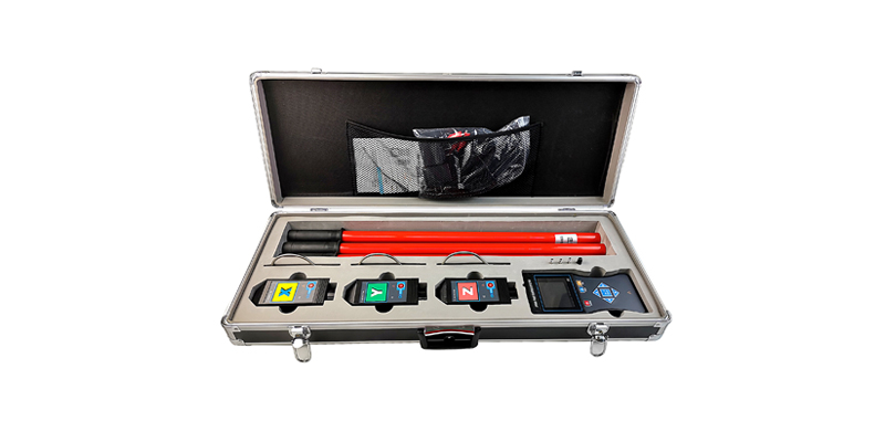
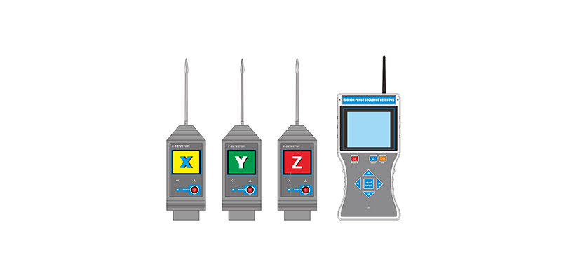
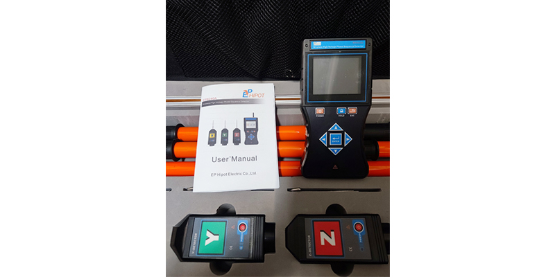
EP8240A Fully intelligent wireless high and low voltage phase sequence detector, referred to as high voltage phase sequence detector, is composed of wireless receiver, XYZ detector, telescopic insulating rod, etc. It is used for phase sequence, phase, voltage, frequency, checking phase test of 400V, 10kV, 35kV and other three-phase circuits, and transformer group judgment. The receiver uses a 3.5-inch true color LCD screen, the same screen displays the phase sequence result, checking phase result, phase, frequency, voltage, vector diagram indication, "X signal is normal, Y signal is normal, Z signal is normal, in phase, out of phase" Wait for voice prompt, three-phase measurement, simple operation, easy to carry, wireless communication distance up to 100m. Among them, bare wires of 35kV and below can be directly contacted for measurement, and bare wires of 35kV and above are used for non-contact measurement. Non-contact testing is to gradually approach the detector to the wire to be tested. When an electric field signal is sensed, the phase sequence and checking phase can be completed. Test, so there is no need to directly touch the high-voltage wire, which is safer! This instrument also has the functions of high-voltage checking phase meter, high-voltage electroscope, high-voltage phase sequence meter, and high-voltage voltmeter.
Technical Specifications:
| High and low voltage three-phase line phase sequence, phase, checking phase, frequency, electrical inspection, voltage test. | |
| Power source | Receiver: DC 7.4V rechargeable lithium battery Detector: DC 3.7V rechargeable lithium battery Continuous work for about 8 hours after fully charging. |
| Transmission method | 315MHz and 433MHz wireless transmission |
| Wireless distance | About 100m |
| Display mode | 3.5 inch true color LCD display |
| Measurement range | Phase checking voltage level: AC 1V~550kV (non-contact type phase checking when more than 35 kV) |
| Voltage: AC 1kV~35kV (When contacting test voltage) | |
| Phase: 0.0°~360.0° | |
| Frequency: 45Hz~75Hz | |
| Resolution | 0.1°, 0.1Hz, 1V |
| Accuracy (23℃±5℃, below 80%RH) | Phase: ≤±10° |
| Frequency: ≤±2Hz | |
| Voltage: ±15%±5dgt (1kV~35kV, high voltage overhead line, other application error ±25%±5dgt) | |
| Phase judge | Phase sequence (phase based on X detector) Phase A: 330°~0° or 0°~30° Phase B: 90°~150° Phase C: 210°~270° Positive phase sequence: X=A phase, Y=B phase, Z=C phase Reverse sequence: X=A phase, Y=C phase, Z=B phase |
| In phase: 330°~0°or 0°~30° Out of phase: 90°~150° and 210°~270° | |
| Voice function | Voice functions such as in-phase, out-of-phase, normal X signal, normal Y signal, and normal Z signal |
| Size of insulation rod | About 3.2m long after extended, about 0.6m long after drawn back. |
| Data storage | 9999 sets |
| Phase checking method | Contact phase checking: When the bare wire voltage is less than 35kV, or less than 110kV with a safety insulation sheath wire, adopt contact phase checking. (operating with an insulation rod) |
| Noncontact phase checking: When the bare wire voltage is more than 35kV, or more than 110kV line, adopt noncontact phase checking. (operating with an insulation rod) | |
| Auxiliary ground wire measurement: when the measurement result is below 100V, if the measurement result is unstable, needs to use the auxiliary ground wire to connect to the ground point to enhance the signal. | |
| Electric indicator | Detector sends out buzz like "beep - beep - beep" |
| Gear shift | Automatic gear shifting |
| Sample frequency | 2 times/s |
| Instrument size | Detector: length width and thickness 145mm×60mm×48mm |
| Receiver: length width and thickness 210mm×100mm×44mm | |
| Backlight | Yes |
| Induction intensity control | According to the intensity of the induced electric field, the detector can automatically control the magnification, which is convenient for the checking phase in densely arranged places. |
| Data maintenance | Press HOLD button under testing mode to maintain the data, and then press HOLD button again to cancel the maintenance |
| Exit function | Press ESC button to exit from current interface and return to the upper directory |
| No-signal indicator | When the receiver does not receive the transmission signal, it dynamically displays “----” symbol |
| Automatic shutdown | About 30mins after startup, the instrument will be automatically shut down to reduce battery consumption |
| Battery voltage | When the battery voltage is low: Detector: the power indicator flashes slowly to promote charging the battery. Receiver: the low battery voltage symbol will be displayed to promote charging the battery. |
| Rated current | Detector: 20mA max. Receiver: 200mA max |
| Weight | Detector: 205g (including battery) |
| Receiver: 395g (including battery) | |
| Insulation rod: 0.5kg for each | |
| Total weight: 5.6kg (including instrument box) | |
| Working humidity and temperature | -10℃~40℃, below 80%Rh |
| Storage humidity and temperature | -10℃~60℃, below 70%Rh |
| Interference | No extra strong electromagnetic field, no interference from other 433MHz or 315MHz signals |
| Insulation intensity | Insulation rod: AC 110kV/rms (between both ends after 5 nodes of insulation rod are totally extended) |
| Detector: 2000V/rms (between both ends of outer shell) | |
| Receiver: 2000V/rms (between both ends of outer shell) | |
| Structure | Anti-dripping Type II and IP63 |
| Safety rules of satisfaction | Satisfy GB13398-92, GB311.1-311.6-8, 3DL408-91 standards and the newly promulgated power industry standard of the state General technical condition DL/T971-2005 for 1kV ~ 35kV portable phase checking device for live work |
| Satisfy IEC61481-A2: 2004, IEC 61243-1 ed.2: 2003 standards |